The Pinhole Camera
|
From The Physics Teacher, December, 1989
Converted to HTML by Pinhole
Visions, 1999
|
Imaging without Lenses or Mirrors
By Matt Young
I like to imagine that the
pinhole camera was the third imaging system invented. First was
the window, which is perhaps half-a-million years old and was invented
for looking through walls. (This is the origin of the old joke,
"Did you hear of the person who invented a device for looking
through walls?' "No, what is it called?"...) The plane
mirror was, I assume, invented just after the beginning of the bronze
age, about 6000 years ago. A little reflection will show that its
function was for looking at yourself. If modern practice is anything
to go by, the inventor was a teenager.
The Greeks apparently understood the principle of the pinhole camera
and developed convex mirrors and burning glasses as well. The Greeks,
however, are not remembered for their ability to putter around,
so the pinhole camera waited in the wings for almost 1500 years.
Alhazen (Ibn Al-Haytham), whom D.J. Lovell 1
called the greatest authority on optics in the Middle Ages, lived
around + 1000 on the Gregorian calendar, invented the pinhole camera,
and explained why the image was upside down. He also studied the
optics of the eye and used the Arabic word for lentil to describe
the lens of the eye. Indirectly, therefore, he gave us the modern
English word, lens, which is the Latin word for lentil.
Leonardo da Vinci may have used the pinhole camera in the 1500s
for his studies of perspective. 2 Around
1600, Della Porta reinvented the pinhole camera. 3
Apparently he was the first European to publish any information
on the pinhole camera and is sometimes incorrectly credited with
its invention. Della Porta's pinhole camera was a large, dark room
with a fairly sizeable hole in one wall. He may have coined the
term camera obscura, which is Latin for dark room. Our English word
camera, therefore, derives from the Latin word for room or chamber.
Della Porta also enlarged the hole and used lenses to cast a sharper,
brighter image, though he was probably not the first to use lenses
in this way.
Despite its antiquity and apparent simplicity, the pinhole camera
offers several advantages over lens optics, particularly when resolution
is not especially important. These include
- complete freedom from linear distortion
- depth of field from a few centimeters to infinity
- wide angular field
The pinhole's light-gathering ability is poor, but this is largely
offset by the high sensitivity of modern films and television cameras.
In addition, pinholes can be used in the ultraviolet and x-ray regions
of the spectrum when reflecting or refracting materials are not
readily available.
Within the last 20 years or so, the pinhole camera has been used
to image x-rays, to provide great depth of field in a flight simulator,
to produce multiple images for integrated circuit masks, for fine
art photography, and to help certain scientists keep their families
well fed. In addition, a few years ago a small company marketed
a pinhole camera that used real photographic film. The camera was
called the PinZip, on the notion that the photons go "Zip"
as they pass through the pinhole and hit the film. There is now
a Pinhole Journal 4 and also a book
on pinhole "fotografy." 5
I take it that you are supposed to pronounce fotografy differently
from photography, but I haven't quite mastered the sounds yet.
Practical Pinhole Cameras
The classic pinhole camera is made by taping a sheet of 4 x 5-
or 8 x 10-in film to the inside of a certain kind of cylindrical
oatmeal box whose manufacturer's name the National Institute of
Standards and Technology's policy forbids me to print. In any case,
the film is taped to the cylindrical part of the box, not the ends,
and a hole is punched into the cylinder opposite the film. The box
is taped shut, and the camera is ready. Purists will use no other
kind of pinhole camera, even though the curved film plane causes
distortion.
You can also make a pinhole camera out of a single-lens reflex
camera body and a cardboard tube or, if you want to get fancy, a
set of extension tubes. You'll have to cover your head with a black
cloth or use an old-fashioned camera with a sports finder, because
it is hard to see anything on the viewing screen. A 100-mm focal
length is convenient and corresponds to a "telephoto"
lens in normal photography. The corresponding pinhole diameter is
about 0.5 mm and is very easily punched into 50-µm (0.002-in) brass
shim stock. Place the shim stock on top of a sheet of corrugated
cardboard. Take a sharp, 0.5-mm sewing needle and tap it gently
with a small tool until it pierces the brass. Grasp the needle between
your thumb and forefinger, rotate it, and force it through the brass.
(With practice, you can manufacture holes under about 0.2 mm. See
Reference 6 for information about an array of precisely
sized, 25-µm pinholes.) Rub both sides of the brass gently with
very fine emery cloth and clean with soap and water.
To attach the pinhole to your camera, you will need lots of black
electrical tape or black masking tape; hence, Mrs. Young's Law:
Science as we know it would not exist if it weren't for masking
tape.
If you use about a 100-mm focal length and a 0.5-mm pinhole, the
F-number will be about 200. The F-number of a lens is the ratio
of its focal length to its diameter and is a measure of the lens's
light-gathering ability. If this ratio is equal to 16, for example,
we write F/16, which is pronounced 'eff sixteen." Typical lenses
have variable apertures that are calibrated with discrete F-numbers
(called F-stops) of 4, 5.6, 8, This is an ascending sequence with
the common ratio of  .
As the F-numbers in the sequence increase, the lens's light-gathering
ability, which is proportional to the area of the aperture, decreases
by factors of 2. Exposure times, or shutter speeds, are similarly
calibrated in factors of 2; typical exposure times, in seconds,
are 1/250, 1/125, l/60, 1/30,.... Every time you increase the F-number
by a factor of
, you must increase the exposure time by a factor of 2. A typical
exposure in outdoor photography is F/11 and 1/100 s. .
As the F-numbers in the sequence increase, the lens's light-gathering
ability, which is proportional to the area of the aperture, decreases
by factors of 2. Exposure times, or shutter speeds, are similarly
calibrated in factors of 2; typical exposure times, in seconds,
are 1/250, 1/125, l/60, 1/30,.... Every time you increase the F-number
by a factor of
, you must increase the exposure time by a factor of 2. A typical
exposure in outdoor photography is F/11 and 1/100 s.
Photographers use a rule of thumb that you can handhold a camera
provided that the exposure time is shorter than or equal to the
reciprocal of the lens's focal length; for our 100-mm pinhole camera,
this means about 1/100 s. Conventional lenses, however, have resolving
powers about equal to 50 lines/mm; the corresponding figure for
the pinhole camera is a few lines per millimeter. You can therefore
tolerate perhaps 20 times more blur due to the shaking of your hand,
so let us say that you can hand-hold your pinhole camera to about
1/5 s.
Another rule of thumb states that the exposure in bright sunlight
is about F/16, with an exposure time equal to the reciprocal of
the film ISO speed. (The ISO speed is a measure of the film's sensitivity;
the higher the ISO speed, the higher the sensitivity.) For example,
if the ISO speed is 400, the correct exposure is about F/16 and
1/400 s. This is about equivalent to F/200 and 1/5 s. Therefore,
with a fast film, you can take pictures in sunlight with your pinhole
camera if you have a steady hand. Otherwise, you will need a tripod.
Theory of the Pinhole Camera
The imaging device of the pinhole camera is a hole punched through
an opaque material. The image of a distant point is simply the shadow
of the hole - or rather the shadow of the material around the hole.
That is, the image is a bright spot on a dark background. When the
hole is large, the image of the distant point is large and displays
a diameter equal to that of the pinhole [Fig. l(a)].
7
An extended object is a collection of points; its image is therefore
a collection of spots. The smaller the spots, the finer the detail
that can be discerned in the object. Therefore, in many ways, the
best pinhole is the one that produces the smallest image of a point.
If we make the pinhole very small in an effort to improve resolution,
we will arrive at the situation depicted in Fig. l(b). Here, the
hole is so small that the pattern of light in the film plane is
an Airy disk: the Fraunhofer, or farfield, diffraction pattern of
the pinhole. 8 In this region,
the smaller the hole, the larger the spot. Evidently, the pinhole
that gives the smallest spot lies in the region between the geometrical
optics region depicted in Fig. l(a) and the region of farfield diffraction
depicted in Fig. l(b).
Fig. 1. Pinhole camera imaging a distant
point.
(a) Large pinhole, geometrical optics.
(b) Small pinhole, farfield diffraction.
Figure 2, a graph of image radius as a function of pinhole radius,
expresses this consideration. When the pinhole is very small, the
image radius r is the radius of the Airy disk, or 0.61 f/s,
where s is the radius of the pinhole and
is the wavelength of the light. (If we express the radius of the
Airy disk in terms of the diameter D of the pinhole, we
get the more common expression 1.22f/D.)
This equality is represented by the hyperbola in Fig. 2. On the
other hand, when the pinhole is large, the image radius r
is equal to the pinhole radius s, as represented by the
line in Fig. 2. f/s,
where s is the radius of the pinhole and
is the wavelength of the light. (If we express the radius of the
Airy disk in terms of the diameter D of the pinhole, we
get the more common expression 1.22f/D.)
This equality is represented by the hyperbola in Fig. 2. On the
other hand, when the pinhole is large, the image radius r
is equal to the pinhole radius s, as represented by the
line in Fig. 2.
Fig. 2. Image radius as a function of pinhole
radius.
The curve intersects the line where 0.6lf/s
= s, or, roughly, where

Neither the hyperbola nor the line accurately represents reality
in this region, yet this is the region we are most interested in
because the pinhole camera gives the sharpest images there. This
is the region between nearfield and farfield diffraction; here,
the image is not amenable to description by simple arguments.
Two-Point Resolution
Usually, we are more interested in distinguishing between neighboring
points or lines than in isolated points. Hence, we change our focus
from image radius to resolution limit - the smallest discernible
separation between two image points. In the farfield case [Fig.
3(a)], when the image of a single point is an Airy disk, the resolution
limit is the radius 0.6lf/s
of the Airy disk. In the geometrical optics case [Fig. 3(b)], we
use a good deal of hindsight and assume that the resolution limit
is 1.5 times the radius s of the image - that is, of the
pinhole itself.
Fig. 3. Limit of resolution. (a) Farfield diffraction,
Rayleigh criterion. (b) Geometrical optics, uniform disks.
In physics you can make your reputation by judicious use of the
first two terms in a Taylor series or by your ability to define
normalized expressions. There seems to be no opportunity to use
a Taylor series here, so let us try normalization. We define normalized
resolution limit as resolution limit divided by pinhole radius and
normalized focal length as focal length divided by s2/.
This allows us to perform experiments with a number of pinholes
or focal lengths and to compare the results. In addition, it allows
us to redraw Fig. 2 as two intersecting lines (Fig. 4) instead of
an intersecting line and a curve. Because of the use of normalized
variables, we can now plot data for any pinhole size or focal length
on a single graph.
Fig. 4. Figure 2 redrawn in terms of normalized
focal length
Experiment
I performed a resolution experiment using as a light source a 650-W,
quartz-iodine lamp intended for home movies. To reduce stray light,
the lamp had to be enclosed in a metal housing and then cooled with
forced air. In addition, since the beam could easily set cardboard
on fire at a distance of 50 or 60 cm, I passed the light through
about 10 cm of distilled water and a heat-absorbing filter. By the
time the water began to boil, I usually needed a break anyway; the
heat-absorbing filter would have cracked with- out the water as
a prefilter. The lamp and the filters illuminated a resolution target
that was in contact with both a ground glass and a gelatin filter
that provided more-or-less monochromatic light at 500 mn.
The target was a three-bar target that had both horizontal and
vertical bars. Figure 5 shows photographs taken with different conditions.
The largest bars in the target have spatial frequency of 1 line/mm.
The photographs in the left column were taken on the axis of the
system; those in the right column were taken 45 off axis. Similarly,
the photographs in the top row were taken with the focal length
of the camera equal to s2/;
those in the bottom row were taken with the focal length equal to
about four-tenths of that value.
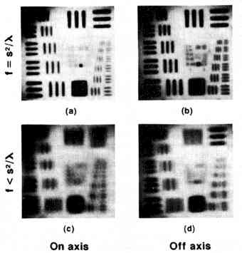
Fig. 5. Resolution target
photographed with a pinhole camera. The largest bars have a spatial
frequency of 1 line/mm. The upper targets were photographed
with the optimum pinhole diameter, the lower with a pinhole several
times larger. Note spurious resolution in (c) and (d) and
astigmatism in (b) and (d).
The sharpest photograph is Fig. 5(a). Figure 5(b) shows astigmatism:
along the right edge, the fifth and sixth horizontal bars are not
resolved, whereas the corresponding vertical bars are resolved.
This is so because the pinhole appears oval when viewed off axis.
Both photographs taken with the shorter focal length also display
spurious resolution. Several of the sets of three bars are unresolved
but appear as two bars, 1800 out of phase with the original three
bars. As a result of astigmatism, the left-most bars of Fig. 5(d)
show both true resolution and spurious resolution at the same spatial
frequency. Figure 6 is easily worth a thousand words, since it explains
spurious resolution with no need for elaboration.
Fig. 6. The cause of spurious
resolution. Three bars (a) well resolved, (b) unresolved, and (c)
displaying spurious resolution.
Figure 7 is a plot of normalized resolution limit as a function
of the focal length of the camera expressed in units of s2/.
The solid lines are the predicted values, as in Fig. 4. The data
were actually taken with three different pinholes under different
conditions. 6 Agreement with the simple
theory is quite good over most of the range. The resolution limit
is smallest when the focal length of the camera is about equal to
s2/,
and there is a (weak) focus at this distance from the pinhole. (The
scale change where f = s2/
somewhat exaggerates the sharpness of the focus.) We could call
s2/
the natural focal length of the pinhole, and, indeed, the pinhole
behaves much like a lens with this focal length. For example, if
you wanted to take a picture of a nearby object, you would apply
the lens equation with f = s2/.
If the object and image distances were not those given by the lens
equation, the pinhole camera would be out of focus and resolution
would suffer. If anything, the pinhole should be a little bit large,
to increase its light-gathering ability. If, however, the pinhole
is about 20 percent larger than optimum, the light-gathering power
will increase by only 40 percent, whereas resolution will worsen
by roughly a factor of 2.
Fig. 7. Experimental data: Resolution
limit in units of the pinhole radius as a function of focal length
in units of the natural local length s2/
of the pinhole. Resolution limit is least when f = s2/
and the pinhole occupies a single Fresnel zone. The hatched region
indicates spurious resolution, which occurs only when the normalized
focal length is less than about 0.4.
Figure 7 also has a hatched area that indicates spurious resolution.
Spurious resolution is found only when the pinhole camera is defocused
so that the image distance is too short for the pinhole or, equivalently,
so that the pinhole is too large for the image distance. We also
find spurious resolution with defocused lenses and, sometimes, in
the images of lenses that have aberrations.
Nearfield and Farfield
Figure 7 can be regarded as a sketch of the way in which light
propagates through an aperture. It is redrawn and annotated as Fig.
8. Close to the aperture, the illuminated area is just the geometrical
shadow of the aperture itself. Farther from the aperture, diffraction
effects begin to become apparent. This is the region of nearfield
diffraction, sometimes called the Fresnel diffraction region. In
this region, the diffraction pattern is not predictable from simple
arguments but consists of concentric bright and dark rings. The
intensity on the axis might be a maximum, a minimum or an intermediate
value. As we approach the distance s2/,
the number of rings decreases, and, finally, the diffraction pattern
becomes one main lobe surrounded by weak rings. Only at the distance
s2/
and beyond does the beam acquire the divergence 0.6l/s
(or 1.22/D)
usually associated with farfield, or Fraunhofer, diffraction. Mathematically,
the pattern does not approach the Airy disk until several times
this distance.
Fig. 8. Figure 7 redrawn to show
the envelope of the beam that passes through an opening. Near the
opening, we see the geometrical shadow; farther away, we see Fresnel
or nearfield diffraction patterns and, finally, Fraunhofer or farfield
patterns. The beam does not acquire the farfield beam divergence
0.61/s
until it has propagated a distance greater than s2/
beyond the opening.
The common remark that you can observe diffraction only when the
aperture diameter approaches the wavelength is therefore not true.
You can observe nearfield diffraction no matter how large the aperture
is. Provided that the edge of the aperture is not rough, the pattern
very close to the aperture closely approximates an edge diffraction
pattern. Likewise, you can always observe a farfield pattern if
you can get far enough away. For example, if the diameter of the
aperture is about 1 mm, or 2000,
the farfield region begins only 0.5 m from the aperture. Similarly,
you can find the farfield distance of an arbitrary or irregular
aperture by squaring a typical dimension and dividing by the wavelength.
Optimum Focal Length
The natural focal length of the pinhole is f = s2/;
with visible light, whose wavelength is about 550 nm, this translates
to a pinhole diameter
when D and f are expressed in millimeters. Since
the optimum pinhole diameter increases as the square root of the
focal length, you can improve the detail in the image by scaling
everything up. For example, if you quadruple both the focal length
and the size of the film, you will retain the same field of view
while only doubling the pinhole diameter. Resolution is thereby
improved by a factor of 2, since the ratio of the film size to the
resolution limit has been doubled. In the jargon of modern optics,
we would say that there are more pixels (picture elements) in the
larger format. In rough numbers, a 35-mm format with 50-mm focal
length is about 180 pixels wide, whereas a 100 x 127-mm (4 x 5-in)
format with 150-mm focal length is about 340 pixels wide, or about
the same as a TV image. Since the picture is two-dimensional, the
larger format carries about four times the information. Nothing
is free, however; the larger format also has a higher F-number,
or lower light-gathering ability, so the exposure time is longer.
Off-Axis Imagery
The ability to expose very wide-angle photographs is limited by
loss of exposure in the corners of the image. The problem is not
unique to the pinhole camera but afflicts nearly all optical systems.
Suppose that a small area is imaged off the axis of the pinhole
camera by angle  (Fig. 9). From the image plane the pinhole appears as a bright spot
of light. The off-axis image is farther from the pinhole by 1/cos
so, according to the inverse-square law, the irradiance there is
less by cos2.
In addition, the pinhole appears smaller by cos
because of the obliquity. Finally, the light falls obliquely onto
the film plane and therefore covers an area 1/cos
larger than the equivalent area on the axis.
(Fig. 9). From the image plane the pinhole appears as a bright spot
of light. The off-axis image is farther from the pinhole by 1/cos
so, according to the inverse-square law, the irradiance there is
less by cos2.
In addition, the pinhole appears smaller by cos
because of the obliquity. Finally, the light falls obliquely onto
the film plane and therefore covers an area 1/cos
larger than the equivalent area on the axis.
Fig. 9. Cosine-fourth law. The exposure off
the axis by an angle
is reduced by the factor cos4.
These three effects combine to reduce the exposure at the off-axis
point by a factor of cos4.
This is the famous and infamous cosine-fourth law. If, for example,
we wish to cover a 60 field of view (30 half-angle), then cos4
30 = 0.56, and we suffer a loss equivalent to one F-stop of exposure
between the center and the edge of the image. For a 90 field, cos4
45 = 1/4 or two F-stops. Most of the time, this is far too much
loss of exposure to be acceptable. You can get around the cosine-fourth
law by using a cylindrical film "plane" centered around
the pinhole. Then, the cosine-fourth law reduces to a simple cosine
law. Since cos 45 = 0.71, you can cover a 90 field with a loss
of exposure of only one-half of an F-stop. That is one reason those
purists like their oatmeal boxes.
Franke's Widefield Camera
In 1979, Franke invented the widefield pinhole camera shown in
Fig. 10. 9 If its index of refraction
is about 1.5, the glass or plastic hemisphere reduces a 90 field
of view to 42. Even a moderate purist like me will agree that this
is a pinhole camera. The actual imaging device is the pin- hole,
and the hemisphere is just a field lens, or a lens that increases
the field of view but does not itself project an image.
Fig. 10. Franke's widefield pinhole camera.
If the index of refraction of the hemispherical field lens is about
1.5, the hemisphere is compressed to a 42 cone.
Franke found that there is slight distortion beyond about 70 because
sin
 ,
and that the best index of refraction would be 1.3. This is the
index of refraction of water, and, in fact, R.W. Wood once submerged
a pinhole camera in water to achieve the same effect.
,
and that the best index of refraction would be 1.3. This is the
index of refraction of water, and, in fact, R.W. Wood once submerged
a pinhole camera in water to achieve the same effect.
Fresnel Zone Plate
The Fresnel zone plate is a relative of the pinhole camera in that
it does not use mirrors or lenses for its imaging properties. Since
the zone plate is covered in most optics books, I will not dwell
on it, except to note that the zone plate is a sort of generalization
or expansion of the pinhole camera in the plane of the aperture.
The zone plate consists of a series of concentric rings, alternately
clear and opaque. It works by blocking diffracted rays that would
have caused destructive interference at the image point.
10 If the radius of the central ring of the zone
plate is s, the focal length of the zone plate is s2/.
The pinhole camera may therefore be regarded as a zone plate with
only one clear zone. Like the zone plate, it focuses by diffraction.
The zone plate, like the pinhole camera, exhibits no linear distortion.
They are the only instruments I know of, except for the plane mirror,
that have this property. In addition, the zone plate can be useful
in the ultraviolet and x-ray regions of the spectrum, for which
other imaging devices are hard to find. Self-supporting gold zone
plates have been manufactured for these spectral regions.
Zone plates have resolution limits comparable to lenses with the
same F-number, and they may be overlapped to form multiple images
spaced by less than the diameter of the zone plates themselves.
Unfortunately, the zone plate has low efficiency and suffers from
veiling glare because most of the light incident on the zone plate
passes through it undiffracted and falls onto the image plane.
Cascaded Apertures
In the late 1960s, researchers at Laval University in Quebec City
generalized the pinhole camera along the axis. They found that they
could place several circular apertures sequentially along the axis
and obtain a focus. 11 The positions
and diameters of the apertures have to be chosen so that each aperture
alone would display a nearfield diffraction maximum at the desired
image point. That is, each aperture must contain an odd number of
Fresnel zones as seen from the image point. If there are N apertures,
the intensity at that point will be increased by approximately N2.
Since energy has to be conserved, this is equivalent to sharpening
the focus.
The experimental work was carried out in the microwave region and
was an attempt to develop low-loss waveguides for communications.
The purpose of the apertures was to keep the electric field away
from the lossy walls of a conventional metallic waveguide. I have
not heard of cascaded apertures since the early seventies and assume
that the idea was rendered obsolete by the development of low-loss
optical fiber waveguides.
Pinspeck Camera
In the early 1980s, Adam Cohen conceived the idea of the pinspeck
camera. 12 (I suggested that he call
his paper "The Joy of Specks," but he did not take this
advice.) At any rate, the imaging device is an opaque spot in the
center of a larger aperture. The spot has to be large enough to
cast a shadow, and the distance from the spot to the screen has
to be well under s2/.
Figure 11 shows how the pinspeck camera works. Each bright object
point casts a shadow of the pinspeck onto the viewing screen. If
there are m resolvable object points, the intensity in
each of the shadows is a fraction (m - 1)/m of
what it is everywhere else. The pinspeck camera casts a very low-contrast,
negative image with several times poorer resolution than a pinhole
camera. Do not, incidentally, confuse the pinspeck camera with the
Fresnel (or Poisson or Arago) bright spot. 13
The latter is a diffraction effect, whereas the pinspeck camera
is based on geometrical optics. Diffraction will only reduce the
contrast of the image.
Fig. 11. Pinspeck camera. The opaque disk
in the center of the glare stop casts a shadow of each bright point
in the object This results in a weak, negative image.
Cohen's work was written up in Scientific American, along with
my work and Kenneth Connors's work on the pinhole camera.
14 As a result of this article, we learned that the
pinspeck camera had been invented just a few years before, when
a group working with x-ray tubes serendipitously discovered the
pinspeck principle because of metal particles lodged inside their
film packs. 15 They now use the pinspeck
camera for imaging the anode of their x-ray tubes so that they can
focus the electron beam onto the anode. Because the pinspeck camera
has better light-gathering capacity than the pinhole camera, the
group does not risk shortening the lifetime of the x-ray tubes just
to focus the electron beam. In a similar way, A.T. Young discovered
the principle of the pinspeck camera due to specks of dust in a
conventional camera and used the images to analyze the performance
of the camera. 16 The contrast
of the pinspeck camera is so low that photon noise affects the image
and limits the camera to very simple objects. 17
Pinhead Mirror
In 1986, Thomy Nilsson, a vision scientist at the University of
Prince Edward Island, accidentally discovered an image of the sun
reflected off a glint in a stucco wall. 18
He correctly interpreted what he had seen and concluded that
a tiny mirror could be used as an image-forming device, behaving
just like a tiny hole. He called the mirror a pinhead mirror and
asked whether it was an undiscovered imaging device.
Even those who remember history are condemned to repeat it. Three
letters in Lasers and Optronics suggested that the pinhead
mirror, like the pinspeck camera, had been invented before. For
example, Donald O'Shea reported using a pinhead mirror to demonstrate
a solar eclipse to a larger number of people than would have been
possible with a pinhole camera. Koheleth said, "Ayn kol chadash
tachat ha-Shemesh" ("There is nothing new under the sun").
Who am I to argue?
References
- D.J. Lovell, Optical Anecdotes, Society of Photo-Optical
Instrumentation Engineers, Bellingham, WA, 1981.
- Ernst Mach, The Principals of Physical Optics (Dover,
New York, n.d.).
- James P.C. Southall, Mirrors, Prisms, and Lenses (Dover,
New York, 1964).
- Pinhole Journal. The Pinhole Resource, Star Route 15,
Box 1655, San Lorenzo, NM 88057.
- Jim Shull, The Hole Thing, A Manual of Pinhole Fotografy
(Morgan, Dobbs Ferry, New York, 1974).
- M. Young, "Pinhole optics," Appl. Opt. 10,
2763-2767 (1971), and references therein.
- M. Young, "Pinhole imagery," Am. J. Phys.
40, 715-720 (1972).
- Matt Young, Optics and Lasers, Including Fibers and Optical
Waveguides, 3rd ed. (Springer, New York, 1986).
- John M. Franke, "Field-widened pinhole camera," Appl.
Opt. 18, 2913-2914 (1979). See also Tung
Hsu, "Reflective wide-angle pinhole camera," Appl.
Opt. 21, 2303-2304 (1982).
- M. Young, "Zone plates and their aberrations," J.
Opt. Soc. Am. 62, 972-976 (1972).
- John W.Y. Lit, "Focussing properties of cascaded apertures,"
J. Opt. Soc. Am. 63, 491-494 (1972).
- Adam Lloyd Cohen, "Anti-pinhole imaging," Optica
Acta 29, 63-67 (1982).
- K.D. Mller, Optics (University Science Books, Mill
Valley, CA, 1988), pp. 161-163.
- Jearl Walker, "The pleasure of the pinhole camera and its
relative the pinspeck camera," Sci. Am. 245
(11), 192-200 (1981).
- A. Zermeno, L.M. Marsh, Jr., and J.M. Hevesi, Imaging by Point
Absorption of Radiation, U.S. Patent 4 085 324, 1978.
- A.T. Young, "Television photometry: the mariner experience,"
Icarus 21, 262-282 (1974).
- M. Young, "Quantum noise limits the pinspeck camera to
simple objects," J. Opt. Soc. Am. 72,
402-403 (1982).
- T.H. Nilsson, "Pinhead mirror: a previously undiscovered
imaging device?," Appl. Opt. 25,
2863-2864 (1986).
- Letters, Lasers and Optronics, July, 1987, p. 12.
 Matt
Young is a physicist with the National Institute of
Standards and Technology, Electromagnetic Technology Division, 325
Broadway, Boulder, CO 80303, and Adjunct Professor at the University
of Colorado. He earned a Ph.D. from the University of Rochester,
Institute of Optics, in 1967 and is especially interested in optics,
optical fiber measurements, and optical image processing. Dr. Young
is the author of Optics and Lasers, Including Fibers and Optical
Waveguides, 3rd Ed. (Springer, New York; 1986) and The
Technical Writer's Handbook: Writing with Style and Clarity
(University Science Books, Mill Vally, CA, 1989). His portrait was
taken with a pinhole camera. Matt
Young is a physicist with the National Institute of
Standards and Technology, Electromagnetic Technology Division, 325
Broadway, Boulder, CO 80303, and Adjunct Professor at the University
of Colorado. He earned a Ph.D. from the University of Rochester,
Institute of Optics, in 1967 and is especially interested in optics,
optical fiber measurements, and optical image processing. Dr. Young
is the author of Optics and Lasers, Including Fibers and Optical
Waveguides, 3rd Ed. (Springer, New York; 1986) and The
Technical Writer's Handbook: Writing with Style and Clarity
(University Science Books, Mill Vally, CA, 1989). His portrait was
taken with a pinhole camera.
Visit his web site at www.mines.edu/~mmyoung
|